

The 3D printed housing of the "pxlDigits" was initially not intended to be "just" a 7-segment display with WLAN.
Originally I built a kind of timer from a two-digit 7-segment display for a friend of mine. She is an elementary school teacher and had the problem that she needed a time display for her students that can also be read by students who are not yet able to read numbers and/or estimate time periods.
For this case, the display of the numbers via the 7-segment display is of course unsuitable. Therefore the display was extended by a 1m long LED strip of WS2812 LEDs and a rotary encoder. Via the rotary encoder the time can then be set, whose period is to run down.
As soon as a time is set, it runs down automatically. The LED strip is fully illuminated at the beginning. As the time runs down, the number of lit LEDs on the LED strip is reduced. In addition, the color of the LED strip changes from green to red.
In principle, this LED strip visually displays the elapsing time. Similar to a loading bar on a computer. Thus, the remaining time for a school assignment can also be read by students who still have difficulties with the numbers.
How to build this timer, called "time_timy", is described in the following article.
Safety instructions
I know the following notes are always kind of annoying and seem unnecessary. Unfortunately, many people who knew "better" have lost eyes, fingers or other things due to carelessness or injured themselves. Data loss is almost negligible in comparison, but even these can be really annoying. Therefore, please take five minutes to read the safety instructions. Because even the coolest project is not worth injury or other trouble.
https://www.nerdiy.de/sicherheitshinweise/
Affiliate links/advertising links
The links to online shops listed here are so-called affiliate links. If you click on such an affiliate link and make a purchase via this link, Nerdiy.de will receive a commission from the relevant online shop or provider. The price does not change for you. If you make your purchases via these links, you support Nerdiy.de in being able to offer other useful projects in the future. 🙂
Requirements
For the assembly you have to master SMD soldering tasks. The following articles contain tips for this.
- Electronics - My friend the soldering iron
- Electronics – Solder THT components by hand
- Electronics – Solder SMD components by hand
Required tool:
Required material:
Collect the necessary parts
To build your own time_timy, you must of course first collect the necessary parts.

For the assembly you need the following parts.
- 2x ready built seven segment digits. See For this: Electronics - Build seven segment digit "pxlDigit" from WS2812 LEDs
- 1x 3D printed case
- 1x 3D printed lid
- 1x Arduino Nano
- 1x rotary encoder
- 10-15cm five-wire cable
- 2x M3 thread inserts
- 1x connection cable for WS2812 LED strip
- 6x M3x6 countersunk screw
- If necessary 5V buzzer
Circuit diagram
In the following you can see the circuit diagram how the single components are wired together.

Overview of the entire circuit diagram.

Close-up of the seven-segment display.

Close-up of the Arduino Nano including the connected components.

Close-up of the Arduino Nano including the connected components.
Insert threaded inserts into the base
So that the housing can later be closed with a lid, this is now prepared.

Adds the M3 threaded inserts...

...with the help of a soldering iron...

...into the recess shown in the housing.

Depending on the quality of the thread inserts, it is now worthwhile to "cut free" the threads of the thread insert again with a tap.
However, if you don't have a tap at hand, you can skip this step.

For testing, you can screw the lid to the case using the M3x6 countersunk screw.

Another view of the screwed lid.
Digits screwed to the base
After you have opened the lid again, you can now screw the seven segment digits to the housing.

Passes the lead to the seven-segment digits to do this through the holes in the housing as shown....

...and screw them together with two M3x6 countersunk screws each from inside the housing.
Make sure that the screws hold by cutting a thread into the plastic of the seven-segment displays. Since this is very thin, you have to be especially careful here and must not tighten the screws too tightly.

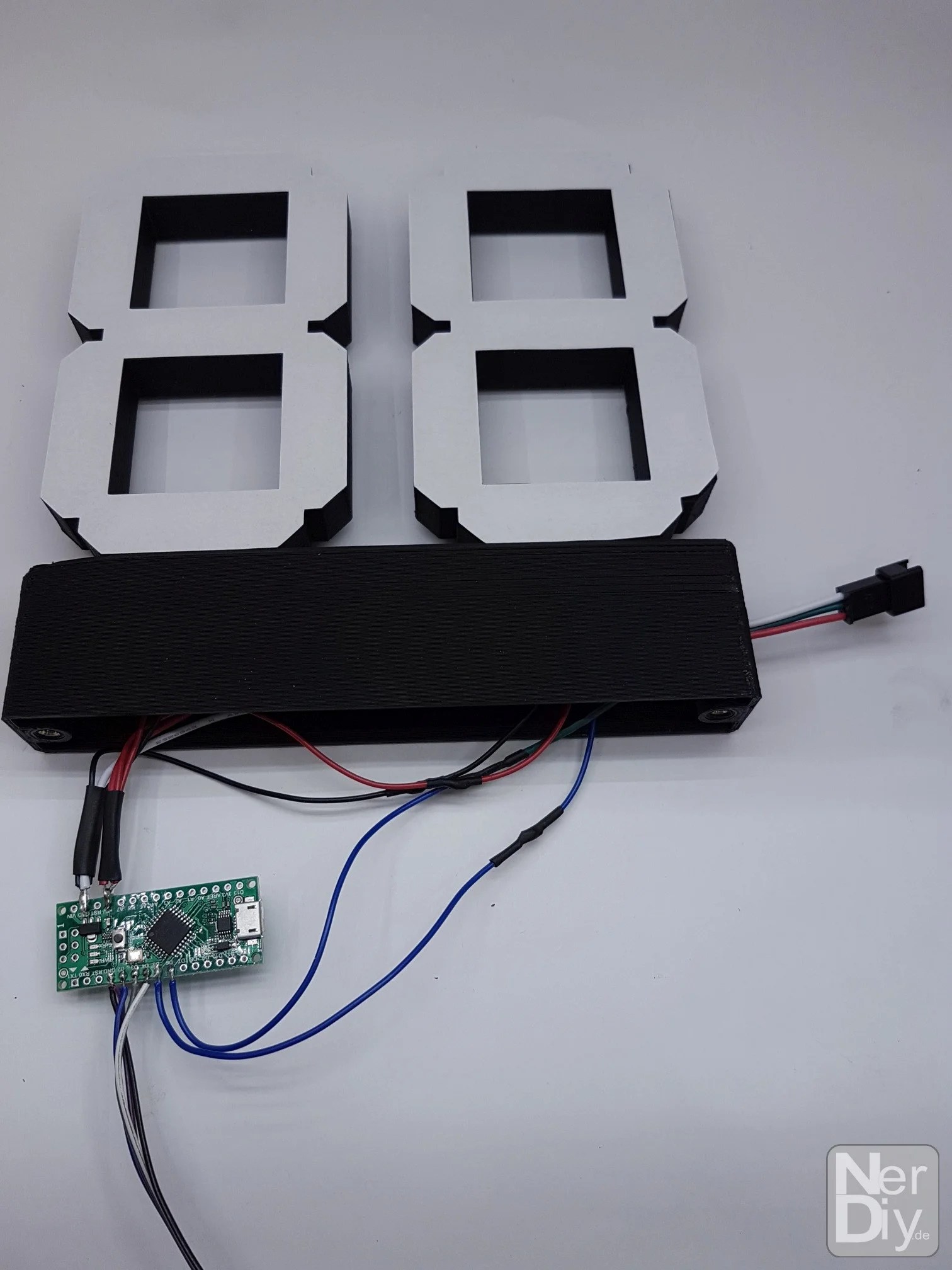
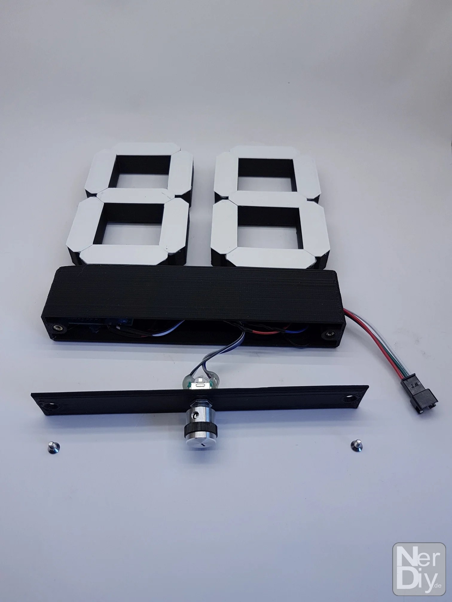
Once you have both digits screwed together, your setup might look like this.
Prepare encoder for installation
The time period to be displayed can later be set and, if necessary, reset via the rotary encoder. For this to work, the rotary encoder must be connected to the Arduino via a short piece of cable.

To prepare the connection of the rotary encoder, you should now first connect the cable to it.
For this you should strip the ends of the single wires about 5mm and tin them with some solder.

Repeat this already for the other end of the lines.

Further view of stripped and tinned wires.

Now you can also prepare the contacts on the rotary encoder by tinning them with some solder.

After that you can solder the prepared wire to the contacts of the rotary encoder as shown.
Prepare Arduino Nano for soldering
In this step, a few initial soldering tasks are performed on the Arduino Nano.

To do this, you should first...

...tin the shown contacts on the Arduino Nano with some solder.
So tin the following contacts.
- +5V
- GND
- D2
- D3
- D4
- D5
- D6

You can now strip the insulation from the connecting cable for the LED strip and tin its ends.
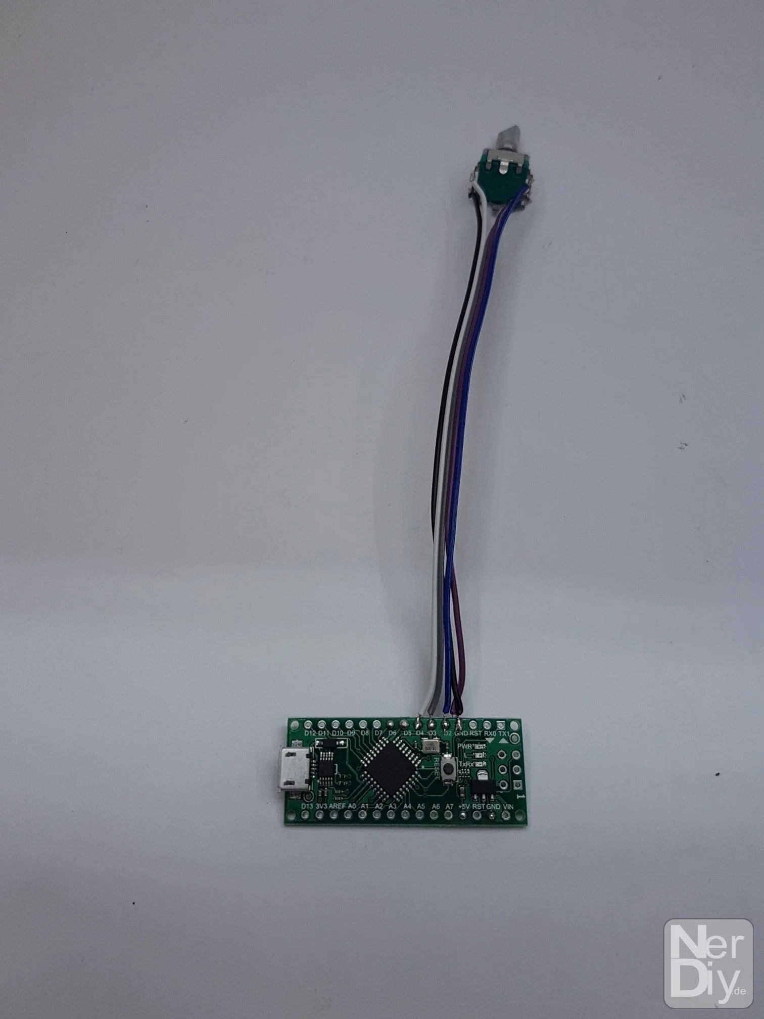
Then you can first connect the connection line of the rotary encoder with...

...solder the Arduino Nano.
You should follow the color coding shown in the picture. (Provided that you have connected the individual lines to the rotary encoder as shown above).

You can now summarize the lines for the energy supply of the seven-segment digits...

... and solder them together.

You should extend the connecting cable for the LED strip by approx. 10cm 🙂 .

Then you can thread the connecting cable for the LED strip through the hole in the side of the housing.

You have now prepared the connection lines for the rotary encoder and the two seven-segment digits.
Solder Arduino Nano with the wires
After you have prepared the lines of the components to be connected, it is now time to connect the Arduino Nano.
To do this, you should now solder the prepared wires as shown.

You can solder the wires according to the following scheme.
| function | Arduino pins |
|---|---|
| DigitInput | D5 |
| LED Strip Input | D6 |
| Encoder A pin | D3 |
| Encoder B pin | D2 |
| encoder button | D4 |
| Digit 5V | 5V |
| Digital GND | GND |
| Encoder GND | GND |
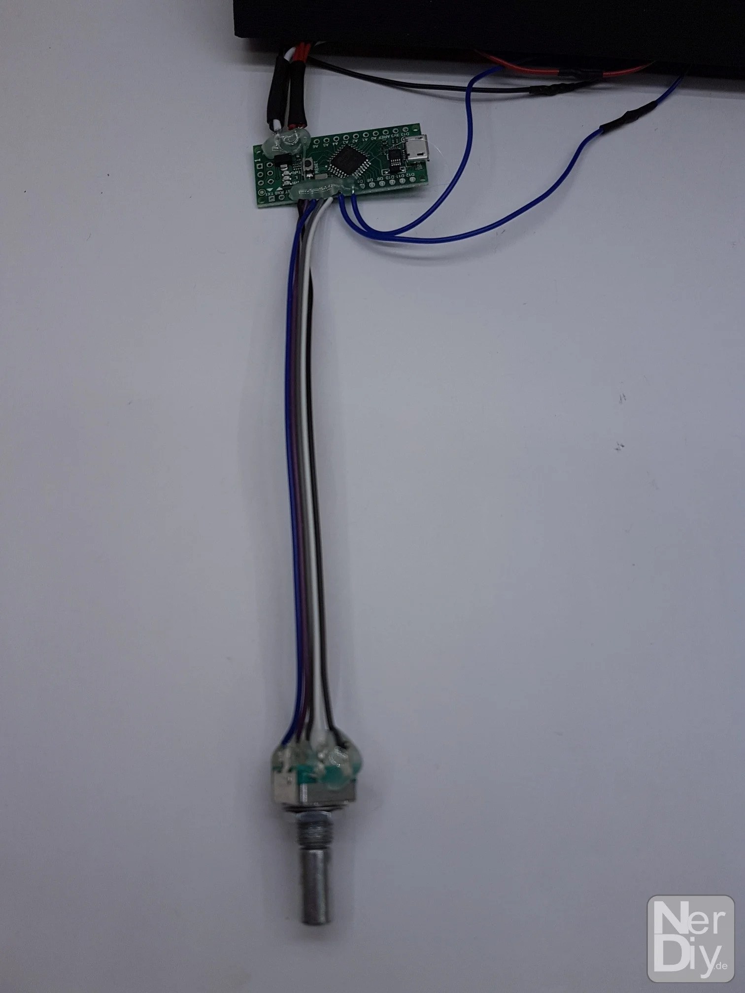
View of the soldered-on rotary encoder.

To mechanically stabilize and insulate the soldered wires, you can now cover the soldering points with some hot glue.
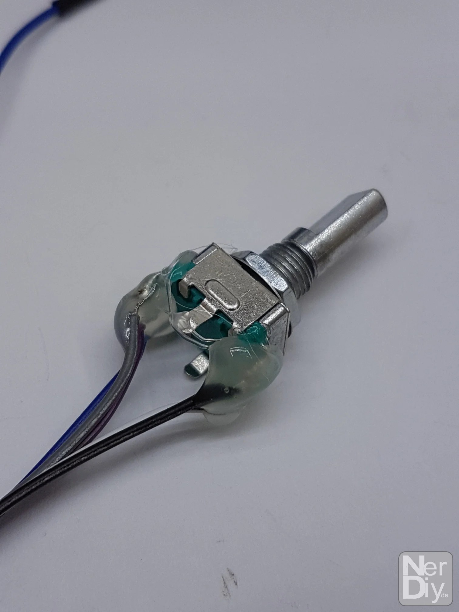
You can repeat the same for the rotary encoder.
Assemble housing
After all electrical connections are complete, you can install the individual components into the housing.

For this you should use the Arduino Nano as shown in the...
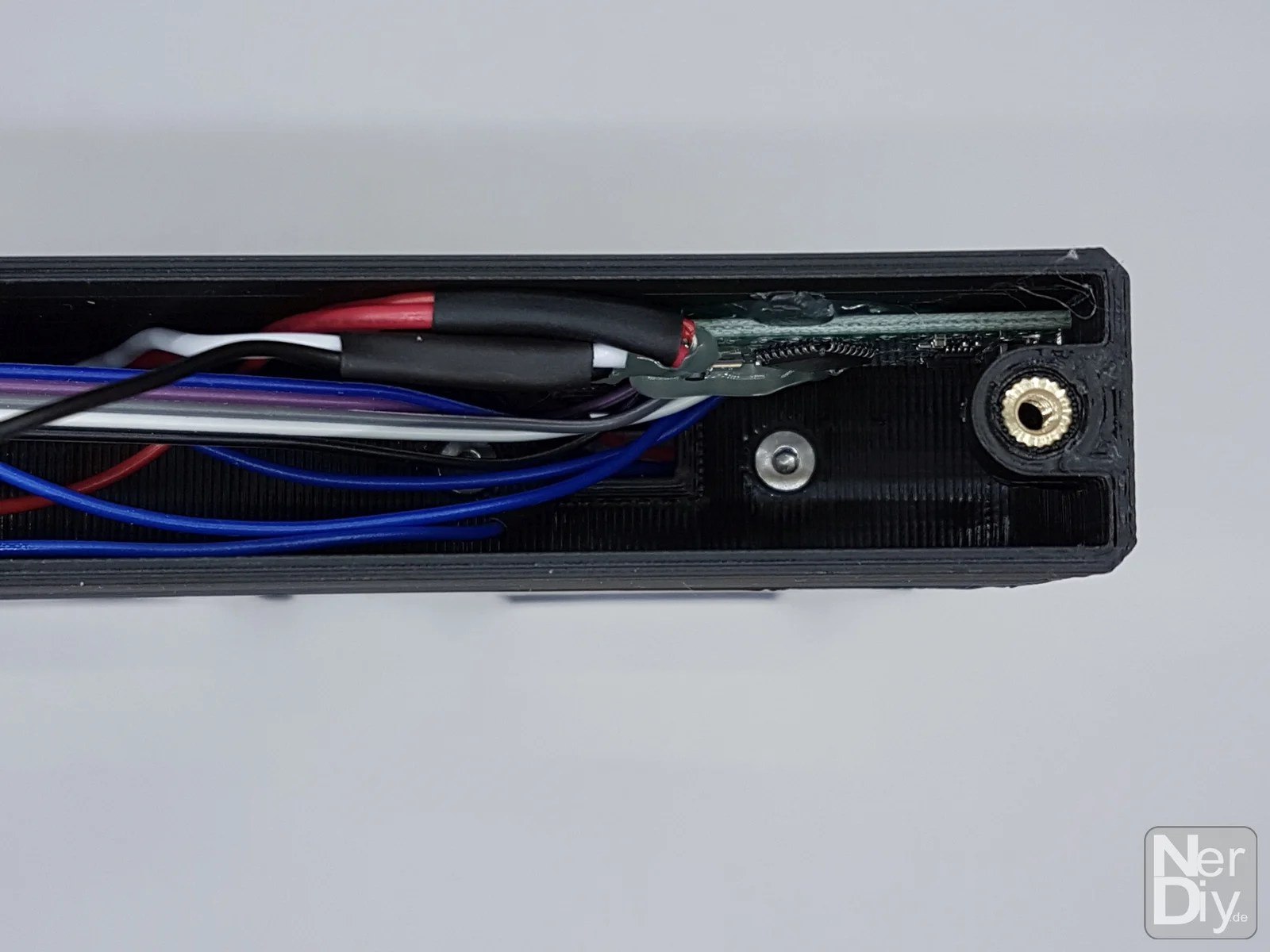
...so in the recess...

of the housing stick that...

...the USB port of the Wemos D1 Mini is accessible from the outside.

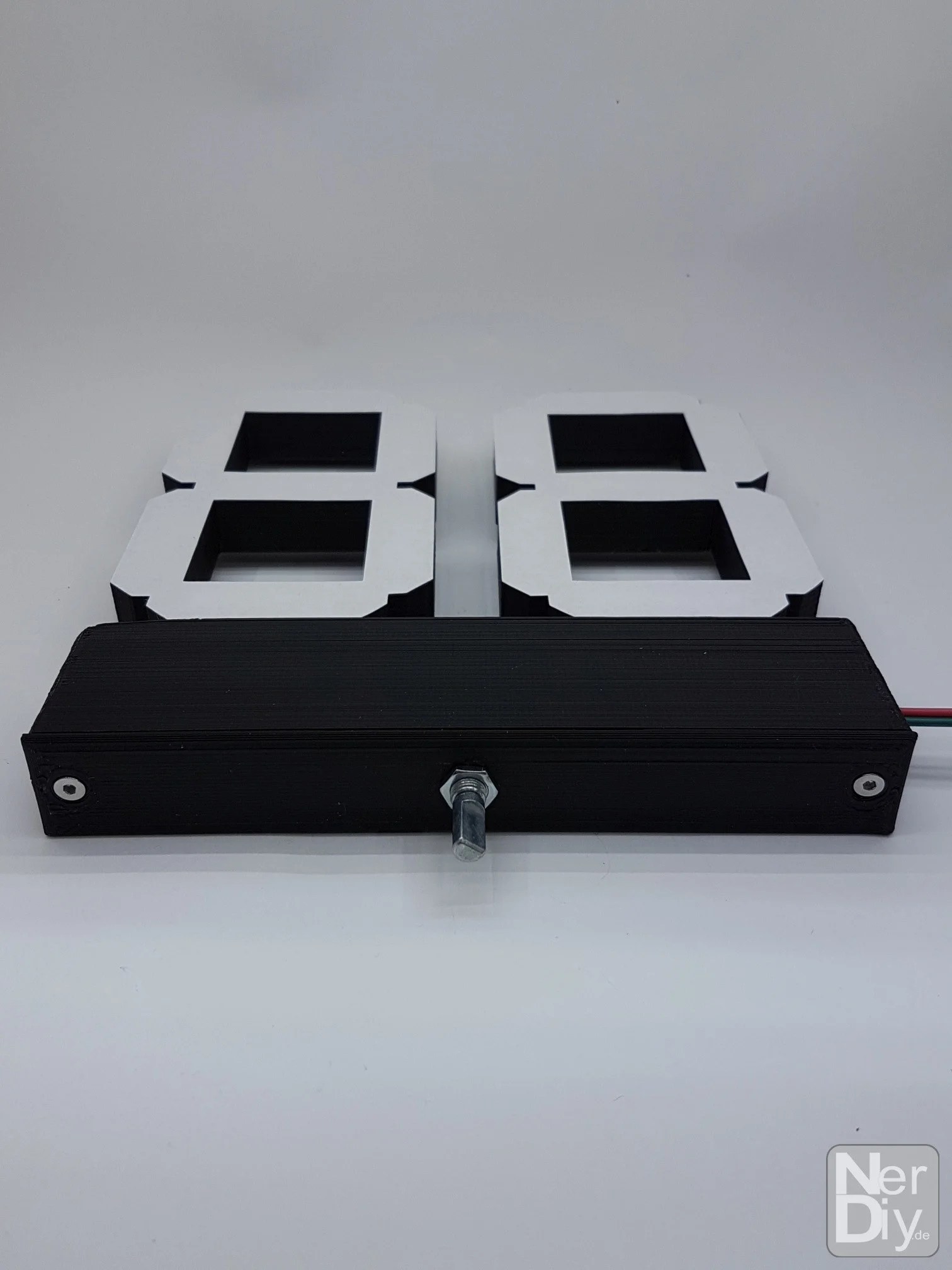
You can then fasten the rotary encoder in the hole in the cover using the nut.
You can then screw the lid to the base using the two M3 countersunk screws.

Another view of the assembled housing.
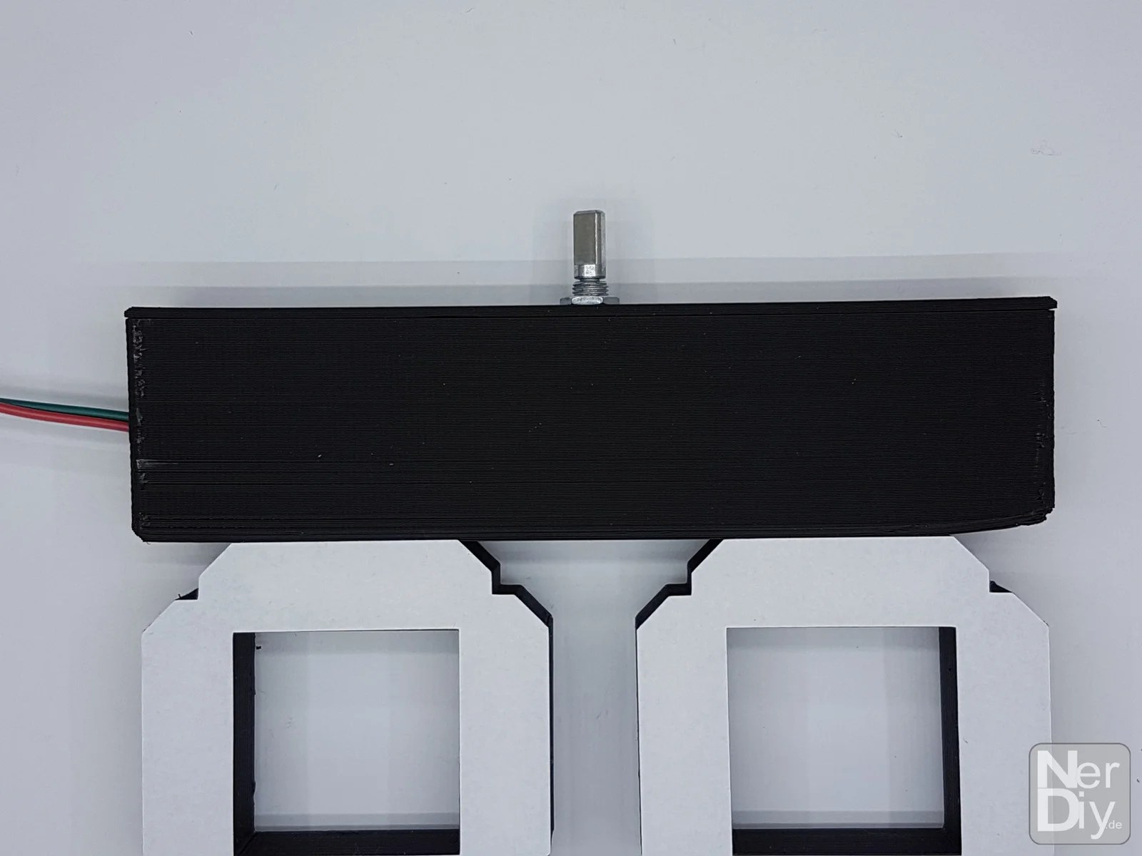
Another view of the assembled housing.

Another view of the assembled housing.

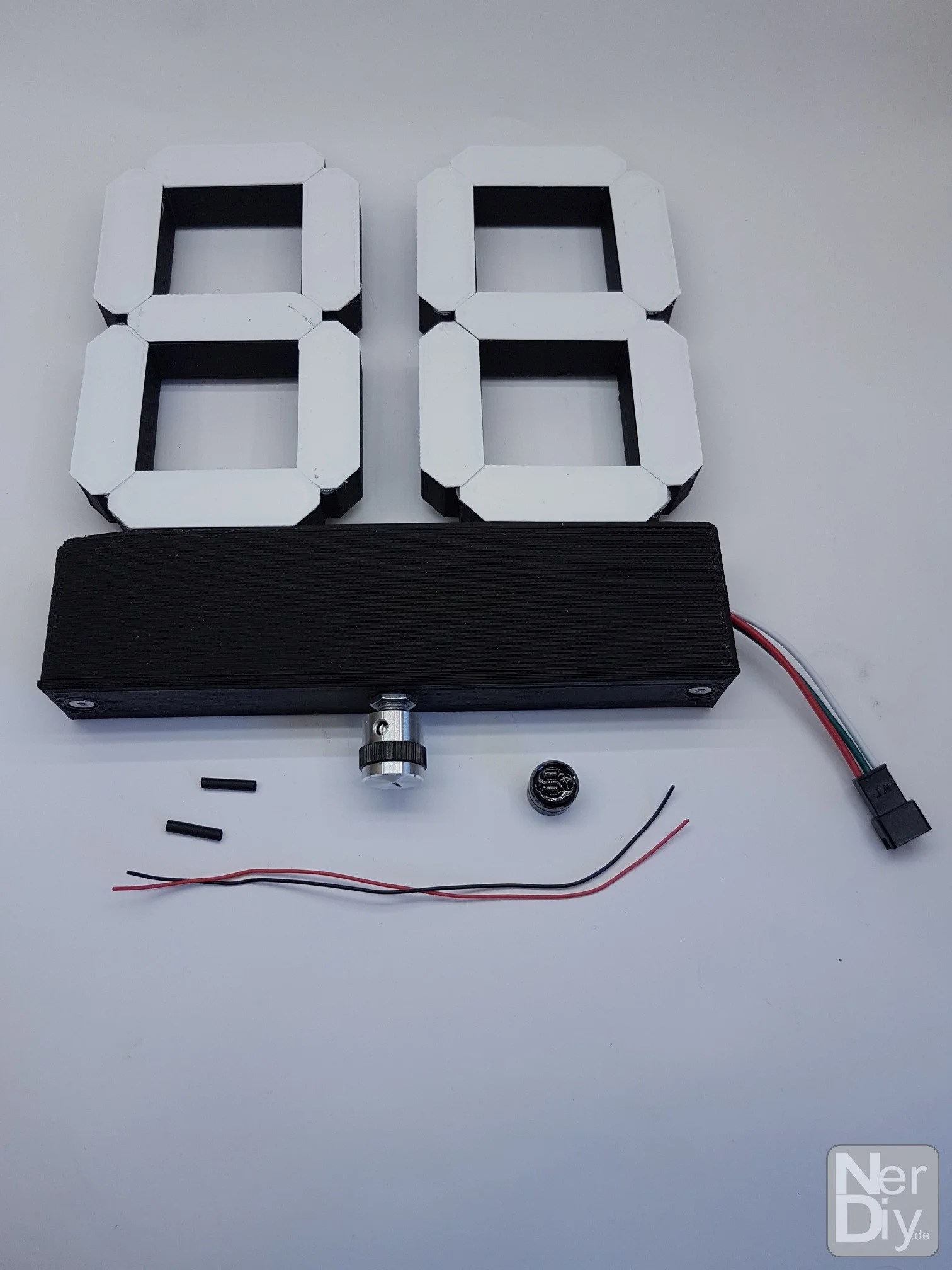
Last but not least, you can add a knob to the...

...onto the rotary axis of the rotary encoder.

Further view of the attached rotary knob.
Attach alternative LED segment cover
I have noticed that the paper front bezels used to cover the LEDs in the seven segment digits lose adhesive strength over time.

An alternative solution for the front panels using 3D printed panels is also described in the article Electronics - Build seven segment digit "pxlDigit" from WS2812 LEDs described.
Optional: Attach buzzer
If you want to be informed acoustically in addition to the visual notification when the set time of the timer has expired, you can also install a buzzer.

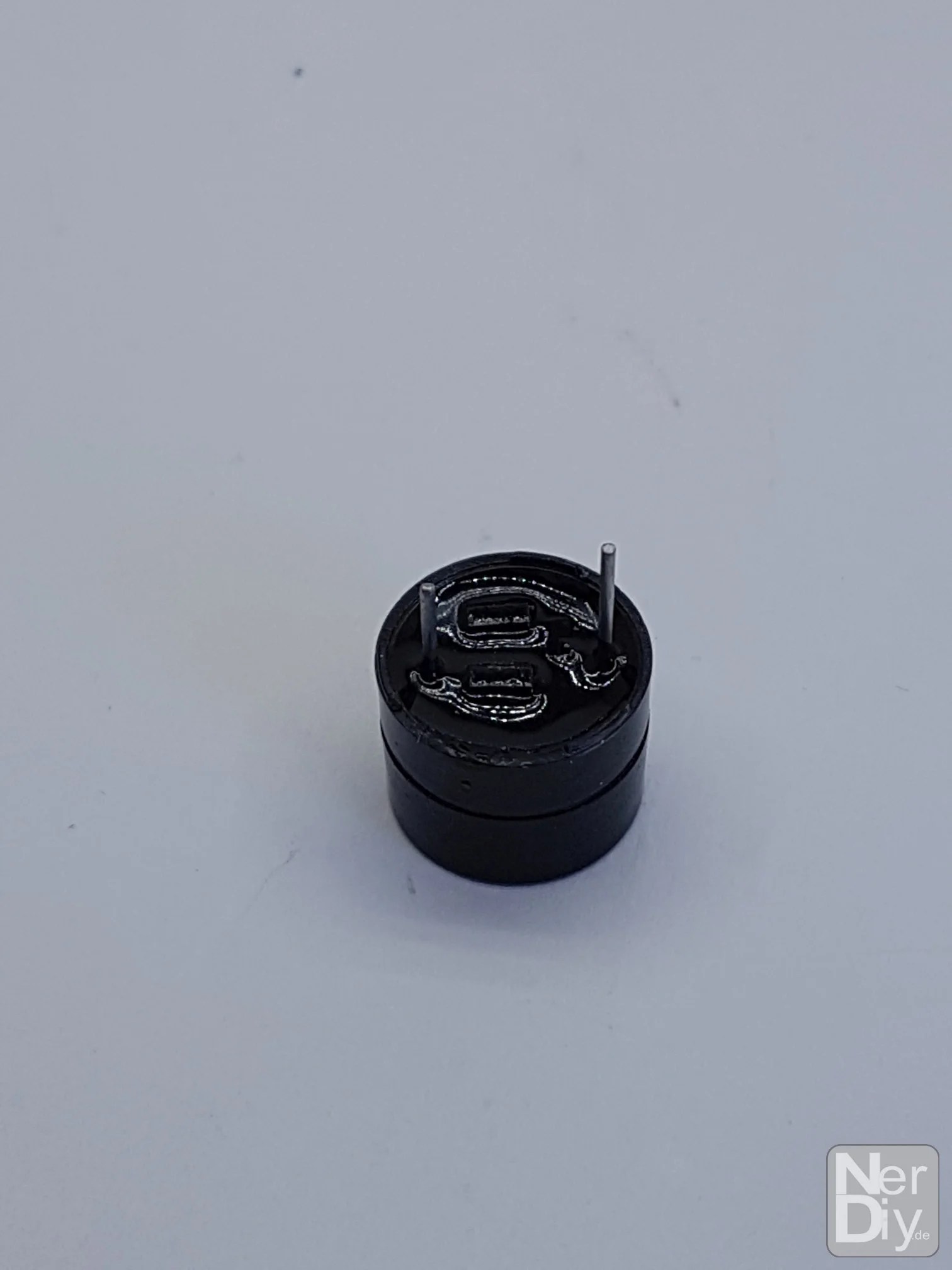
For this you need a 5V tone generator/buzzer, two shrink tubes of about 20cm length and two wires of about 10cm length.
Another view of the parts needed.
To install the buzzer, you first have to open the case again.

Then prepare the wires by stripping the ends about 5mm each and tin them with some solder.
Now you can connect the prepared wires with the contacts of the buzzer....

...soldering.

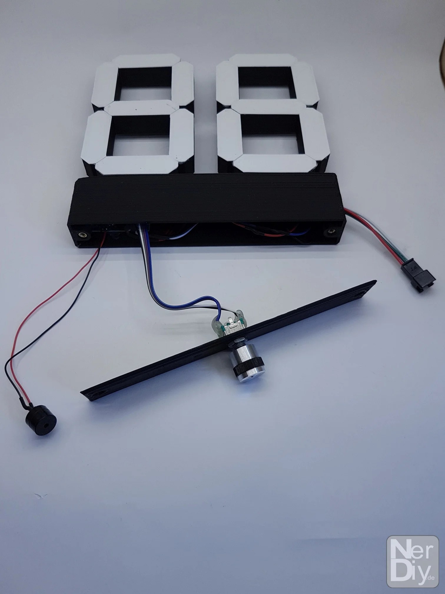
Close-up of the soldered wires.

Close-up of the soldered wires.

You can then use the heat shrink tubing to protect the contact points against short circuits.

In addition to the rotary encoder, there is also a hole in the lid.
Behind this, the buzzer will be mounted later.
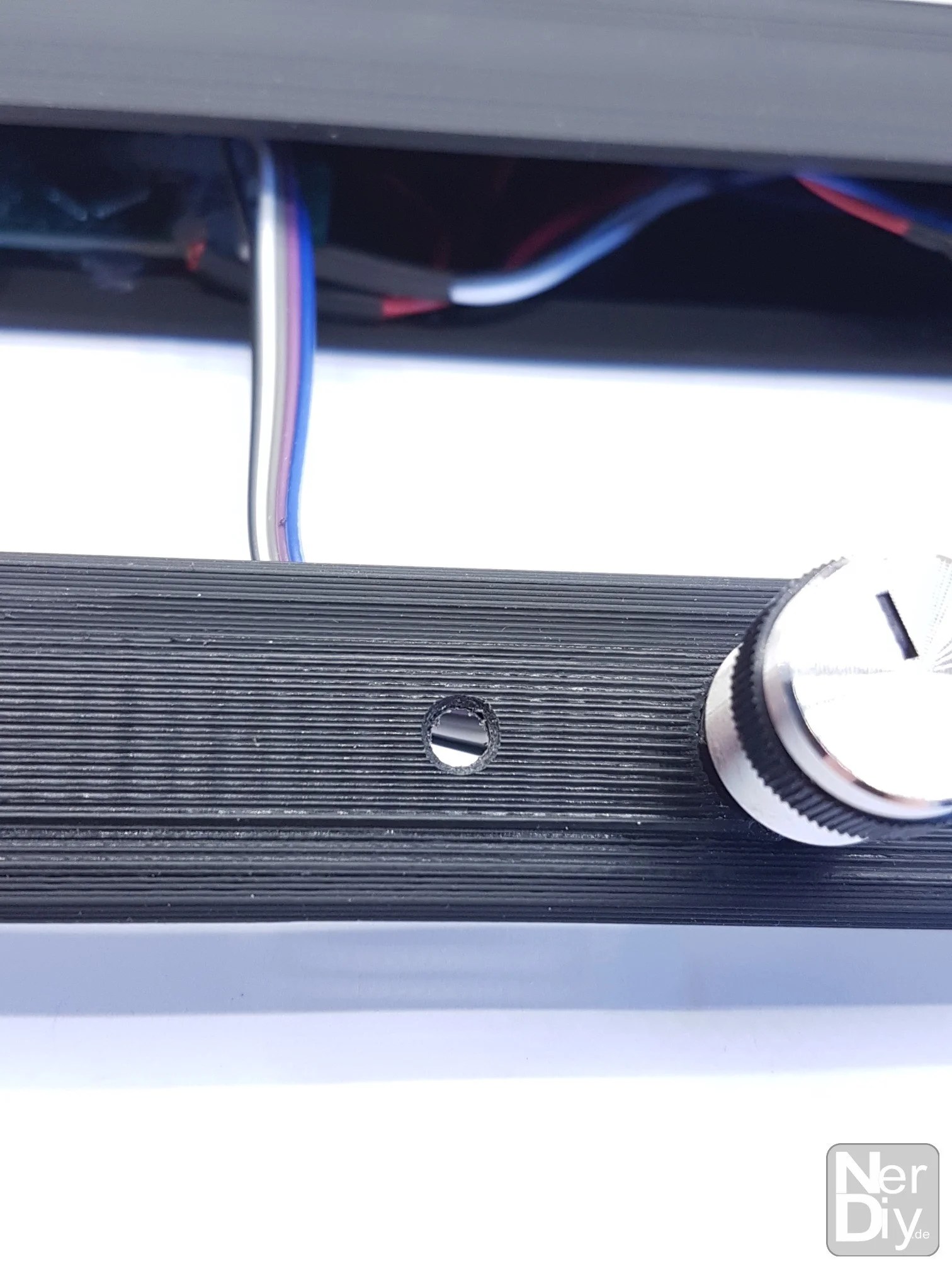
Close-up view of the hole.

Now, however, the first step is to connect the buzzer.
Tin the contacts "A1" and "A2" of the Arduino Nano with some solder.

Then you can solder the connection lines of the buzzer - as shown - to the Arduino Nano.
Your setup should now look something like this.

Now you have to fix the buzzer with some hot glue over the hole so that the hole in the buzzer is congruent with the hole in the lid.

The glued buzzer should then be in about...

... look like this.
It is important that the hole in the buzzer is congruent with the hole in the lid and that no hot glue covers the hole in the buzzer.
Only in this way can the sounds of the buzzer also penetrate to the outside.

Other view.

After that, you can screw the lid back onto the housing.
Upload software with the Arduino IDE
The Arduino code to run the "time_timy" can be found in the following Git repository.
How to download files from a Git repository is described in the article GitHub - How do I copy files from a Git repository to my computer? described.
Tips for programming the Arduino code on the Arduino Nano can also be found in the article ArduinoIDE - Tips and Tricks.
Attach the LED strip
Unfortunately I don't have any photos of the complete setup including the LED strip. But you can get a very good overview of the complete setup in the following video.
You only need to connect the LED strip to the prepared connector. Often these LED strips are delivered including the connector used here. Your LED strip should consist of 90 WS2812 LEDs. If you use more or less LEDs you can adjust this number in the Arduino code using the parameter "NUMPIXELS_BAR".
Power supply
You can power the "time_timy" via the USB socket of the Arduino Nano. Make sure that the power supply you use is protected against overvoltage, overcurrent, short circuit and all other possible failures. I have also linked a power supply that you can use in the material list.
The power consumption of the LEDs is reduced by the configuration in the Arduino Sketch. You should not change these values without adjusting the power supply.
Have fun with the project
I hope everything worked as described for you. If not or you have questions or suggestions please let me know in the comments. I will then add this to the article if necessary.
Ideas for new projects are always welcome. 🙂
PS Many of these projects - especially the hardware projects - cost a lot of time and money. Of course I do this because I enjoy it, but if you think it's cool that I share the information with you, I would be happy about a small donation to the coffee fund. 🙂
![]()
![]()