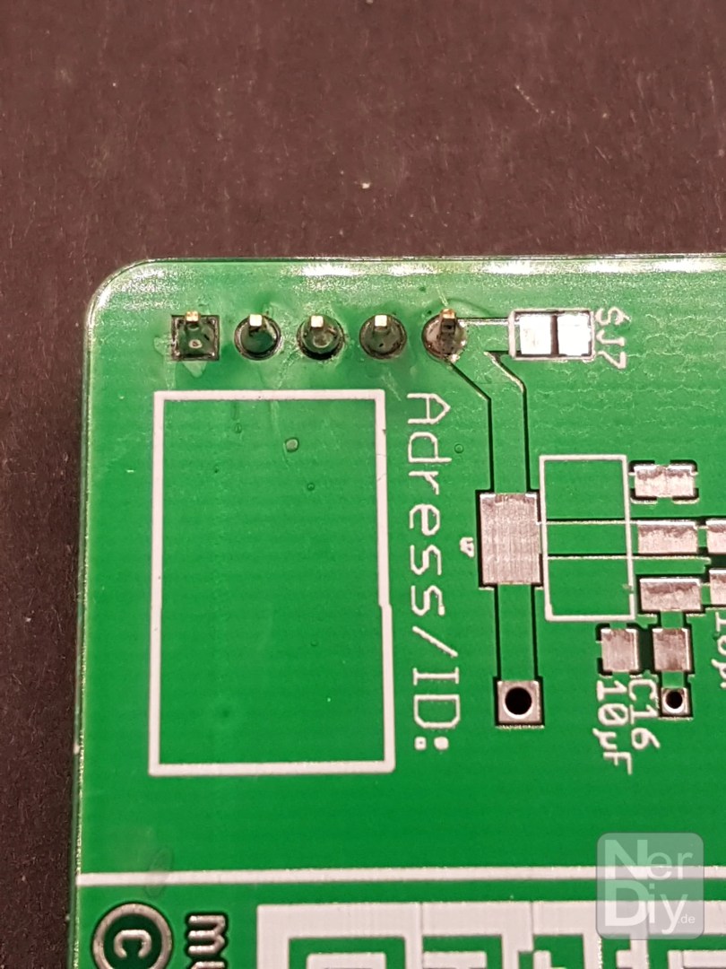
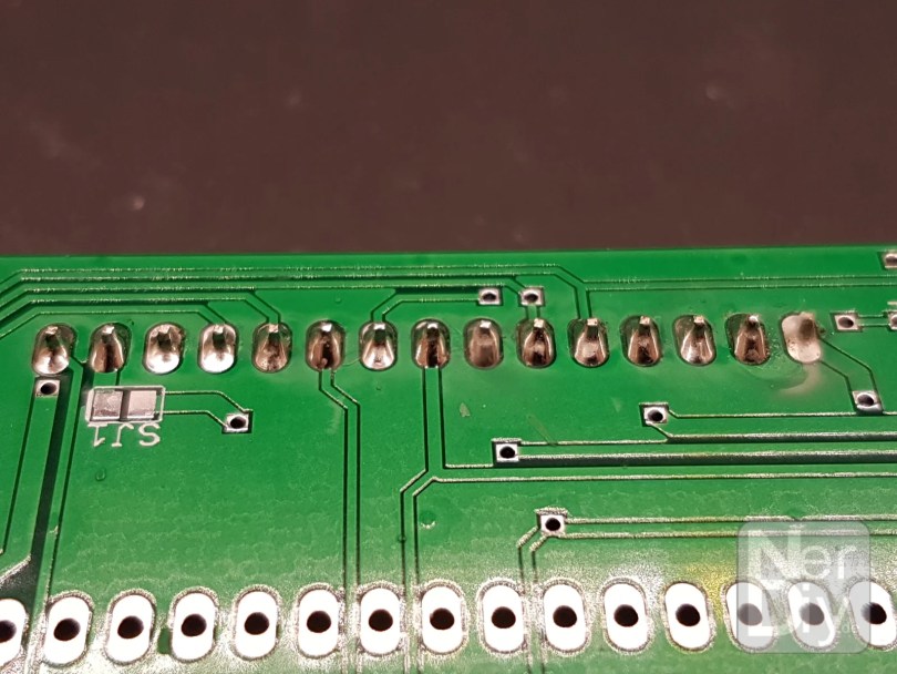
Soldering THT components (THT = Through Hole Technology) is one of the basics you need to build kits, prototypes and the like. This is because many electronic components, especially ICs, are still available in this "through-hole" version.
Modern/new components in particular are often only used as SMD variant Nevertheless, this assembly technology is indispensable - especially in the DIY sector.
The following article describes what you need to consider when assembling PCBs with THT components and how to proceed.
Safety instructions
I know the following notes are always kind of annoying and seem unnecessary. Unfortunately, many people who knew "better" have lost eyes, fingers or other things due to carelessness or injured themselves. Data loss is almost negligible in comparison, but even these can be really annoying. Therefore, please take five minutes to read the safety instructions. Because even the coolest project is not worth injury or other trouble.
https://www.nerdiy.de/sicherheitshinweise/
Affiliate links/advertising links
The links to online shops listed here are so-called affiliate links. If you click on such an affiliate link and make a purchase via this link, Nerdiy.de will receive a commission from the relevant online shop or provider. The price does not change for you. If you make your purchases via these links, you support Nerdiy.de in being able to offer other useful projects in the future. 🙂
Requirements
Helpful articles:
You can find more helpful information on the basics of soldering in the following article:
Electronics - My friend the soldering iron
Electronics - Solder connections, clean and remove components
Required material:
In the following list you will find all the parts you need to implement this article.
Required tool:
In the following list you will find all the tools you need to implement this article.
General procedure
The general procedure for soldering THT components can almost be summarized as a general rule.
- Insert the component from above - i.e. the side with the placement print - correctly oriented through the PCB.
- Fix the component. In most cases, a small strip of sellotape/adhesive tape is sufficient for this. Sometimes you can also bend the legs slightly apart on the underside.
- Turn the circuit board over and solder (only) the first contact to the circuit board.
- Check the correct orientation of the component again. (An error has been quickly corrected at this point).
- If necessary, heat the solder joint again to align the component properly.
- Solder the remaining contacts.
Resistors/capacitors
To be added.
JST sockets
JST sockets are basically just reverse polarity protected and latching connectors. They are available in various pitches and as THT or SMD components. This example shows how a JST connector is assembled as a THT component.


Pin headers
Pin headers are basically the big brother of JST plugs/sockets. Compared to these, they only have the disadvantage that they are not reverse polarity protected and the connectors on the pin headers do not lock into place.
Pin headers are available in both THT and SMD versions.
However, soldering the pin headers is just as easy as soldering the JST connectors.


Tub plug
Tub connectors are another relative of pin headers. In principle, as the name suggests, these connectors are pin headers that are surrounded by a kind of "trough". These are used in particular in conjunction with flat cable connectors. These can be plugged into the tray connectors to prevent polarity reversal.


Post bushes
To be added.
ESP8266
Many of the ESP8266 boards are available either as a version with a pin header (for example on a Wemos D1 Mini) or as an SMD component. In the first case, you can solder the ESP8266 or its pin headers like a normal pin header. The soldering of the second case - i.e. as an SMD component - is described in the article Electronics – Solder SMD components by hand under the paragraph ESP8266 ESP-12 described.
IC sockets can save IC lives
Especially when soldering ICs in DIL housings, there is a small but simple tip that can save you a lot of time and effort if the worst comes to the worst. For each type of DIL housing there are suitable sockets that can be soldered in place of the IC. The desired IC is then plugged into these sockets later.
Should a defect occur in the IC in question, it can simply be replaced. So you save yourself the trouble of unsoldering and re-soldering. In addition, the probability that you will destroy or damage the IC due to excessive temperatures during the soldering process is virtually zero.
The (low) additional material costs for the IC socket are therefore worthwhile in any case.


THT push-button
Soldering THT push-buttons is particularly easy. This is because they snap into place so well when they are inserted at the mounting location - thanks to appropriately bent contacts - that they are already aligned and can be soldered directly.


SMD push-button
The soldering of SMD buttons is described in the article Electronics – Solder SMD components by hand under the paragraph SMD push-button described.
5mm and 3mm LEDs
To be added.
Closing and opening solder jumpers
Solder jumpers are a great way to add modifications or adjustable options to the PCB in advance without giving up the "professional look".
Later, various options and settings can be activated or deactivated by opening or closing this soldering jumper.
The solder jumper is closed by placing or removing a solder bridge over its two contacts.


Further information
Have fun with the project
I hope everything worked as described for you. If not or you have questions or suggestions please let me know in the comments. I will then add this to the article if necessary.
Ideas for new projects are always welcome. 🙂
PS Many of these projects - especially the hardware projects - cost a lot of time and money. Of course I do this because I enjoy it, but if you think it's cool that I share the information with you, I would be happy about a small donation to the coffee fund. 🙂

