

In recent years, the ESP8266 has increasingly become the universal forest and meadow microcontroller that can be used in almost every project. Otherwise, you can only find a microcontroller for ~2€ including WiFi and with plenty of memory in its big brother, the ESP32.
The ESP8266 is available in different versions. The most common version, because it is certified, is the ESP-12 version with all its sub-variants. This allows you to use almost every GPIO and also the ADC, which is not always the case with other versions. However, this version has one “disadvantage”…
A bright blue LED on the ESP's PCB is practical to see whether the ESP is being supplied with energy. However, in projects in which the ESP8266 should be installed as invisibly as possible, this is quite annoying.
But there are ways to get rid of this LED. How this works and what you need to pay attention to is described in the following article.
Contents
Safety instructions
I know the following notes are always kind of annoying and seem unnecessary. Unfortunately, many people who knew "better" have lost eyes, fingers or other things due to carelessness or injured themselves. Data loss is almost negligible in comparison, but even these can be really annoying. Therefore, please take five minutes to read the safety instructions. Because even the coolest project is not worth injury or other trouble.
https://www.nerdiy.de/sicherheitshinweise/
Affiliate links/advertising links
The links to online shops listed here are so-called affiliate links. If you click on such an affiliate link and make a purchase via this link, Nerdiy.de will receive a commission from the relevant online shop or provider. The price does not change for you. If you make your purchases via these links, you support Nerdiy.de in being able to offer other useful projects in the future. 🙂
Requirements
Helpful articles:
In the case of the hardware solution, you should have already spent some time with the soldering iron.
You can do this in the article Electronics - My friend the soldering iron find further information.
Required material:
- none -
Required tool:
In the following list you will find all the tools you need to implement this article.
The software solution
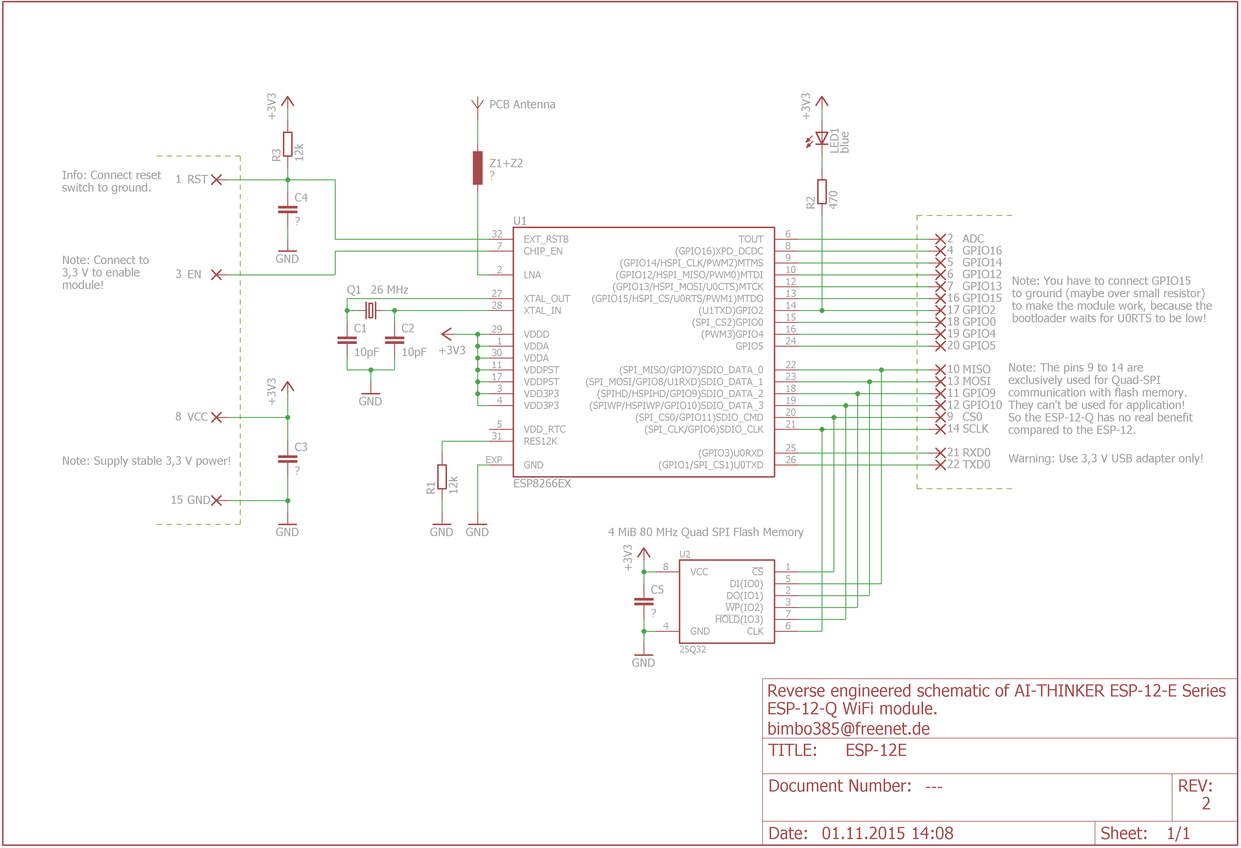
The simpler solution to the “LED problem”, for which you don’t need a soldering iron or other tools, is the software solution. A look at the circuit diagram of an ESP8266 in version 12 shows that the cathode of our problem LED (“LED1” in the circuit diagram) is connected to the GPIO02 via a resistor. And where there is a GPIO, there is also a switching option via software. 🙂
It should be noted that the switching logic of this LED is inverted because the LED is connected to the GPIO with its “negative pole”. This means that with a HIGH level at GPIO02 the LED is switched off, while with a LOW level it is switched on. This must be taken into account when switching the GPIO2.
If you program your ESP8266 yourself using the Arduino IDE, the following code is enough to deactivate the LED.
#define GPIO02 2 pinMode(GPIO02, OUTPUT); digitalWrite(GPIO02, HIGH);
If, on the other hand, you happen to use ESPEasy as the “operating system” for the ESP8266, you can use the following, already integrated function.

The hardware solution
The hardware solution is the solution of your choice if you want to deactivate the LED but still use the GPIO02 to interact with other hardware. The LED is simply unsoldered. The GPIO02 or D4 in particular is often used on Wemos D1 mini boards - at least by me - because it is located right next to the “5V” and “GND” pins. The only disadvantage: The LED is usually destroyed, but in most cases this can be tolerated.


This is admittedly the most radical solution. At the same time, it is also the only solution to deactivate the LED if you want to use the GPIO02 for other outputs at the same time.
Further information
https://vietnhap.com/dien-tu-so/tom-tat-esp8266-va-phan-loai-cac-ho-esp.htm
Have fun with the project
I hope everything worked as described for you. If not or you have questions or suggestions please let me know in the comments. I will then add this to the article if necessary.
Ideas for new projects are always welcome. 🙂
PS Many of these projects - especially the hardware projects - cost a lot of time and money. Of course I do this because I enjoy it, but if you think it's cool that I share the information with you, I would be happy about a small donation to the coffee fund. 🙂
![]()
![]()