

The pxlBlck_RingClock is the pxlBlck_SlotClock very similar. It is also constructed using a 1×60 LED matrix and can display the time according to the same scheme as the pxlBlck_SlotClock.
However, the LED strip in the pxlBlck_RingClock is installed in a ring and not in a disk. This makes the design of the clock even more unobtrusive. The microcontroller for control is built into the base of the pxlBlck_RingClock.
You have the choice between a minimalist base in which the ESP8266 is housed as compactly as possible. If, on the other hand, you want a little more stability and perhaps even space for an RTC, you can also build the pxlBlck_RingClock with the larger base. If you also install the RTC, you can also use the pxlBlck_RingClock without an active WiFi connection.
All information about the structure of the pxlBlck_RingClock can be found in the following article.
Safety instructions
I know the following notes are always kind of annoying and seem unnecessary. Unfortunately, many people who knew "better" have lost eyes, fingers or other things due to carelessness or injured themselves. Data loss is almost negligible in comparison, but even these can be really annoying. Therefore, please take five minutes to read the safety instructions. Because even the coolest project is not worth injury or other trouble.
https://www.nerdiy.de/sicherheitshinweise/
Affiliate links/advertising links
The links to online shops listed here are so-called affiliate links. If you click on such an affiliate link and make a purchase via this link, Nerdiy.de will receive a commission from the relevant online shop or provider. The price does not change for you. If you make your purchases via these links, you support Nerdiy.de in being able to offer other useful projects in the future. 🙂
Requirements
For the assembly you have to master soldering tasks. The following articles contain tips on this.
- Electronics - My friend the soldering iron
- Electronics – Solder THT components by hand
- Electronics – Solder SMD components by hand
Required tool:
Required material:
In the following list you will find all the parts you need for the assembly.
Overview
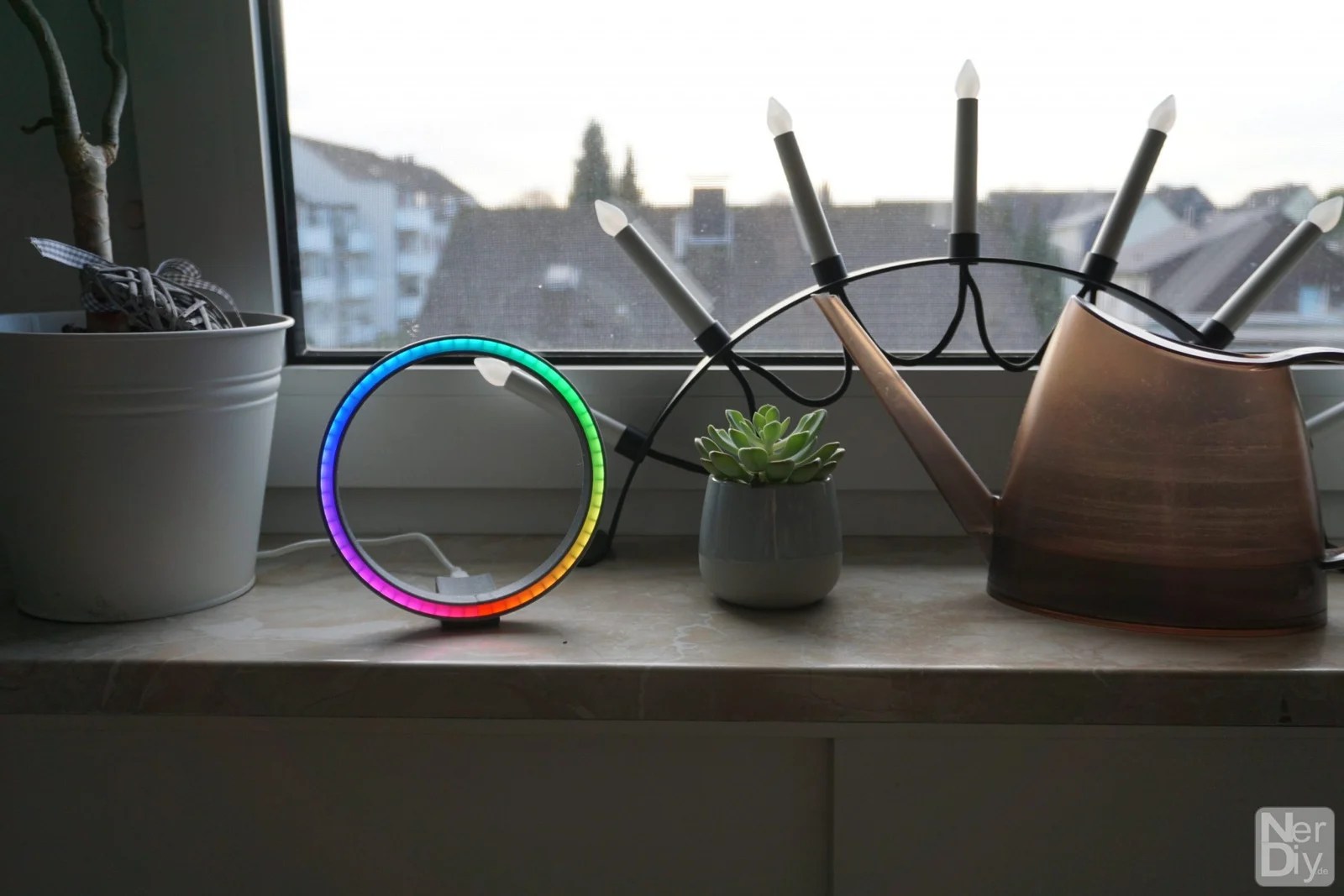
Here you can see a small overview of how the display of the pxlBlck_RingClock can look. As usual, the colors of the minute, second and hour hands and the hour marker can be set. The brightness of the hour markers and the hands can be set independently of each other.


Collect the necessary parts
Before you can start building your pxlBlck_RingClock, you should first collect all the parts you need.

To build the pxlBlck_RingClock you need the following parts.
- WS2812 LED strip 144LEDs/m 60LEDs long
- 3D printed LED holder
- 3D printed base (different versions are available)
- 3x cable approx. 10cm long
- 1x Wemos D1 Mini
- 2x 2×8 self-tapping screws
- 1x acyl glass ring inner diameter: 130mm, outer diameter: 141mm, thickness: 3mm
- 2x M8x40 cylinder head screw

Another view of the ring parts.
You can find the STL files for printing on your 3D printer in the repository for the pxlBlck_RingClock under the following link.
Updated 02/16/2021
Olivier has created an STL with which the LED ring can be printed from transparent PLA. He has kindly agreed that it may be linked here. Many thanks again 🙂 You can find the STL on Thingiverse under the following link.
Screw the LED ring to the mini base
There are different versions of the base. The socket shown here is the smallest of the available sockets. It only contains the ESP8266. (More does not fit in there). Due to its low weight, the pxlBlck_RingClock stands upright, but also tips over quickly. You should therefore only use this base if the planned installation location is level. As an alternative pedestal, there are pedestals below which can also be weighted down with additional weights. There is also a little more space in one of these bases. For example, an RTC (real-time clock) can also be integrated into the base.

Screw the base to the LED holder as shown. To do this, you can use the M2 screws and nuts shown or self-tapping 2×8 screws.

Another view of the screwed base with the LED holder.

Another view of the screwed base with the LED holder.
Prepare LED strips
Before you can insert the LED strip into the base, you should solder the connecting cables to it.

To do this, remove 5mm of the insulation at each end.

Then...

Place the LED strip in front of you so that the arrow points away from you. This is important as the data input of the LED strip is on this side.

Now you should prepare the first contacts with some solder. This will make soldering the cables a little easier later on.

Solder the wires, then as shown...

... to the prepared contacts of the LED strip. Wires are soldered to the following contacts.
- G
- 5V
- DIN

Another view of the soldered cables.

To make it easier to insert the LED strip into the LED holder, you should now carefully bend the red cable so that all cables lead away from the LED strip in the same direction.
Important: Make sure that you do not put too much strain on the contact surface of the SMD strip. Otherwise it could happen that the wire including the contact surface tears off.

Close-up of the bent cable.
Insert LED strip into LED ring
Once you have prepared the LED strip, you can now insert it into the LED holder.

To do this, guide the cables through the LED holder and the screwed-on base as shown.

Then you can start inserting the LED strip into the LED holder from the lower "6 o'clock position".

The LED strip should be pushed into the LED holder as far as it will go.

Another view of the inserted LED strip.

Another view of the inserted LED strip.
Insert acrylic glass ring
You should now insert a suitable LED ring into the LED holder as a diffuser.

To do this, place the diffuser on the LED holder...

...and presses it evenly around the entire circumference into the LED holder.

The diffuser should ultimately sit flush in the LED holder.

View of the previous structure.
Connect the ESP8266 to the LED strip
Your pxlBlck_RingClock should now look pretty much finished. However, the heart of the clock - the ESP8266 - is still missing.

For this you need the ESP8266. As is often the case, I recommend using the Wemos D1 Mini. The ESP8266 is installed on this.

You can now connect the Wemos D1 Mini to the prepared connection cables of the LED strip.

To do this, the LED strip must be connected according to the following diagram.
| ESP8266 | LED strips |
|---|---|
| 5V | 5V |
| G | G |
| D4 | DIN |

Further view of the connected ESP8266.
Connect LDR to ESP8266
We recommend installing an LDR so that your pxlBlck-RingClock can also automatically adjust the brightness of the LED strip to the ambient brightness. This is a little fiddly due to the limited space in the socket, but it's worth it in the end 🙂

For this you need an LDR and a "normal" (1/W) 1k resistor.
Some shrink tubing (not shown in the picture) is also very helpful.

Solder the 1k resistor then...

...to the contacts of the Wemos D1 MIni as shown.
The resistor is soldered between GND and the input of the ADC. It thus functions as a series resistor to the LDR and forms a voltage divider in combination with the LDR.

Close-up of the soldered resistor.

Close-up of the soldered resistor.

You must now solder the LDR between the contacts of the analog digital converter and 3V3.

To do this, you should protect at least one of the LDR contacts against short circuits with heat-shrink tubing.
The LDR itself should then protrude approx. 5mm beyond the end of the board of the Wemos D1 Mini.

Another view of the installed LDR.
Insert ESP8266 into mini-base
After you have connected the LDR to the Wemos D1 Mini, it can now be inserted into the base. If you want, you can also wait and test the function first. Simply skip this part and program and test the pxlBlck_RingClock first. It is also no problem to remove the Wemos D1 Mini later.

To insert the Wemos D1 Mini into the base, you should slide it into the base as shown.

Make sure that no SMD components on the Wemos D1 Mini are damaged or torn off.
You should be able to insert the Wemos D1 Mini without much effort.

The LDR should peek out lightly at the end.

If you want, you can then bend the LDR up a little and "align" it even better to the ambient light.

Other view.

Another view of the assembled pxlBlck_RingClock.

Another view of the assembled pxlBlck_RingClock.

Another view of the assembled pxlBlck_RingClock.

Another view of the assembled pxlBlck_RingClock.

Another view of the assembled pxlBlck_RingClock.
Structure of the pxlBlck RingClock including RTC (Real Time Clock)
The pxlBlcks always obtain the correct time via an NTP server which they reach using the WiFi connection. However, sometimes you want to set up the pxlBlcks at a location where no WiFi connection is available. In this case, the missing source for a correct time can be replaced by an RTC. An RTC (Real Time Clock) keeps the set time in a battery-buffered state. This means that the time is not lost even without a power supply.

You will need the following parts to build the pxlBlck_RingClock, including accommodation for an RTC.
- WS2812 LED strip 144LEDs/m 60LEDs long
- 3D printed LED holder
- 3D printed base (now the larger version which is also available in the Git repository).
- 3x cable approx. 10cm long
- 1x Wemos D1 Mini
- 2x 2×8 self-tapping screws
- 1x acyl glass ring inner diameter: 130mm, outer diameter: 141mm
- 2x M8x40 cylinder head screw
If you also want to connect the LDR (see below for more information), also connect the following parts.
- LDR
- 1k resistor 1/4W
- approx. 3cm shrink tube

Another view of the required components without the "ring parts".
Connecting the RTC to the ESP8266

Of course, you will need the Wemos D1 Mini and an RTC to set it up.

Start now with the preparation of the RTC by...

...you carefully bend the tub rail...

... and then pull off the plastic part.

You can now use the bare contact tabs as a kind of assembly aid.

Connects the RTC to the Wemos D1 Mini as shown...

... and glues the RTC to the Wemos D1 Mini using a drop of hot glue.

Now you can remove the contact tabs by heating them briefly with a soldering iron. It is very helpful to use tweezers or pliers to pull out the contact tabs while they are being heated with the soldering iron.

The contacts of the RTC should then look as shown.

Now you have to connect the RTC to the I2C bus of the ESP8266 and the supply voltage.
To do this, run a first line from contact "D" of the RTC to contact "D2" of the ESP8266.

Repeat this with another line between contact "C" of the RTC and contact "D1" of the ESP8266.

Close-up view of the soldered I2C bus connection.

You can now establish the ground connection between the RTC and ESP8266. To do this, solder a wire...

... between the "-" contact of the RTC and the "G" contact of the ESP8266.

Last but not least, the RTC must of course also be connected to the 3.3V power supply.

To do this, solder a wire between the "+" contact of the RTC and the "3V3" contact of the ESP8266.

Another view of the fully connected RTC.
Connect the LDR to the ESP8266
This step is optional. With the help of a connected LDR, you are able to configure your pxlBlck so that it adjusts the brightness of the connected LED matrix to the ambient brightness. This means that the brightness of the connected LED matrix is dimmed when the ambient light becomes darker and increased when the ambient light becomes brighter.

To do this, you must first connect the 1k resistor shown between the "GND" and "A0" contacts of the Wemos D1 Mini.
An example of how you can do this very compactly is shown in the picture.

Make sure that there are no short circuits to the neighboring components.

You then have to solder the LDR to the top of the Wemos D1 Mini as shown.
It is advisable to insulate the bare connection legs of the LDR with some shrink tubing.

The "head" of the LDR should be soldered so that it protrudes approx. five to ten millimeters beyond the end of the circuit board of the Wemos D1 Mini.
Connect the ESP8266 to the LED strip
Now that you have prepared the Wemos D1 Mini, you can continue with the connection to the LED strip.

Solder the connecting cables of the LED strip to the Wemos D1 Mini as shown.
You can connect the contacts of the LED strip to the contacts of the Wemos D1 Mini according to the following diagram.
| ESP8266 | LED strips |
|---|---|
| 5V | 5V |
| G | G |
| D4 | DIN |

Other view.
Insert the ESP8266 into the base
Now that you have connected all parts to the ESP8266/Wemos D1 Mini, you can install the Wemos D1 Mini in the socket.

To do this, slide it - with the RTC in front - into the recess in the base as shown.

Make sure that no components on the PCB of the Wemos D1 Mini are torn off or wires are pinched.

The Wemos D1 Mini should be able to be pushed into the recess without much effort.
Installing weights in the stand
If you want to make your pxlBlck_RingClock more stable, you can equip the base with additional weights.

The M8x40 cylinder head bolts shown, for example, are quite suitable for this purpose.

You can simply use these...

...into the recesses in the base of the pxlBlck_RingClock.

To keep them in place, you should fix them in the base with a drop of hot glue 🙂
Program firmware
After setting up the pxlBlck_RingClock, you must now install ESPEasy including the pxlBlck plugin on the ESP8266. How to do this is described in the following article.
Configure pxlBlck plugin
After installing the firmware you have to configure the plugin correctly. You can also find information about this in the article pxlBlck - Install and configure the pxlBlck plugin.
For additional orientation, you can also use the settings from the screenshot shown here.

Configure LDR to set the display brightness
In order for the LDR to be read out by ESPEasy and the current brightness of the LED matrix to be updated accordingly, you must first make a few configurations. How to do this is described in the following article.
Setting the LED offset and alignment
As the LED strip can be installed in different ways, you may need to adjust the display.
To do this, you can set the offset of the "twelve o'clock position" from the start of the strip. You can find this setting in the plugin's web menu in the section "12 o'clock LED position". It is best to play around here until you have found the correct value. For better orientation, you can also use the "Thick 12 o'clock mark" activate. This way you can easily see where the 12 o'clock position of the dial is and adjust the offset so that it is at the top position.
In the event that your RingClock is running in the wrong direction, you can change the "direction of rotation" using the "Direction Inversed" Reverse option.
Configuration of the RTC under ESPEasy
To be able to use the RTC in combination with ESPEasy, I have written another plugin. I will soon describe its configuration in a separate article and then of course add it here or post it on Nerdiy.de.
Everything you need to know to configure it correctly can be found here:
pxlBlck Usecases
Articles are listed under the tag "pxlBlckUsecase" in which you can find examples of use. It also explains how you have to configure your pxlBlck for this.
Animations, icons and commands
More information about the display of animations, icons and the possible commands with which you can configure your pxlBlck can also be found in the following articles.
- pxlBlck - Configure and display animations
- pxlBlck - design icons, transfer them to the pxlBlck and display them
- pxlBlck - Commands for configuring the pxlBlck
Have fun with the project
I hope everything worked as described for you. If not or you have questions or suggestions please let me know in the comments. I will then add this to the article if necessary.
Ideas for new projects are always welcome. 🙂
PS Many of these projects - especially the hardware projects - cost a lot of time and money. Of course I do this because I enjoy it, but if you think it's cool that I share the information with you, I would be happy about a small donation to the coffee fund. 🙂
![]()
![]()
Hello,
Thank you for the detailed and very good description. I recreated the whole thing (had a strip with 60LED lying around here), but I noticed that there is a jump / gap of 1 second when jumping from one end (supply) to the other end; do you have an idea what could be the reason?
I'll email you a little video...
Joachim
Good evening Joachim,
did you flash the pre-compiled binary? I recently fixed a bug that looks very similar to this one. However, I had only corrected the error in the code and had not yet updated the binary. I'm working on that. So you can either flash the firmware with the Arduino IDE or wait 10 minutes. By then I should have updated the binary.
Please let me know if that fixed the error. 🙂
Best regards
Fabian
Hello and thank you for the very detailed instructions. Unfortunately I've been waiting for a while for the 3D printer financed via Kickstarter and I'm sure I'll wait a little longer. Do you have an idea where I can have the 3D parts printed or is there another reader who can print the parts for me for a fee?
I still want to order all the other missing components and I noticed that you didn't specify the thickness of the acrylic ring anywhere. Since this should sit flush, the information would certainly be helpful. Thanks!
Kind regards from the Lower Rhine
Patrick
Hey Patrick,
thanks for the hint with the thickness for the plexiglas ring. I added the info (3mm).
As for printing the parts: I'm happy to do that too. Just contact me via the contact form if you are interested and then we can clarify it. 🙂
Best regards
Fabian
Hello Fabian,
Thank you for the detailed instructions!
Two questions: how thick is your acrylic glass for the cover? 3mm?
And even more interesting: How did you cut the acrylic glass?
Best wishes and a "Happy New Year"!
Olivier.
hey oliver,
Thanks and thanks for the hint with the thickness for the plexiglass ring. I added the info (3mm). I have the ring with me http://www.acrylformen.de/ be cut by laser. Unfortunately the shop is currently closed (as far as I know due to high demand). But there are also other shops that offer this service. Unfortunately I can't recommend any specific ones. 🙂
Happy New Year and best regards'
Fabian
Hello Fabian,
I was thinking about building a larger version of the clock (3D model may have to be printed in several parts). The LED strips are available as standard in different "densities" (number of LEDs/m). I have created a calculator for the different variants, which calculates the diameter and the magnification factor (for 3D printing). I have released the calculator: https://docs.google.com/spreadsheets/d/1NKIeCsHsKDcRir4_VSnpM0GEaJx69tWigmRbGMM3S2I/edit?usp=sharing
or.: https://bit.ly/2JAXHnR
You are welcome to link it in the article or use the table with the most common LED variants.
Greeting,
Olivier.
hey oliver,
super cool thing! Thanks a lot for this. I would include that in the article. Should I send you/your blog/etc. how to link? 🙂
Thanks and best regards
Fabian
Hello Fabian,
You are welcome to link to my blog: https://huf.org
Haven't made an article about it yet though
Best regards,
Olivier.
All right, thank you! Habs just entered and linked to your blog. Thanks again for that! 🙂
Best regards
Fabian
Hello !
I'm trying to download your STL from the github link but when I open the downloaded files in Cura, I have an error anf It won't load. I'm used to download stl files from "thingiverse" or "Cult3d" but here, there is something in the link I can't figure out .
Can you help me to get those files?
Thank you for your inspirational work!
Hey Matt,
Thanks for pointing that out. I got a similar complain in the past and investigated whats going on here. It looks like that gitHub does not delivering the STL file itself at downloading it but the page to display a preview of it. I have to find another way to offer the files here. Until then please download the complete repository (containing the stl files). The following link should work: https://github.com/Nerdiyde/pxlBlck/archive/main.zip
The STL files should be located in pxlBlck\platform\pxlBlck_RingClock
I hope this works for you. If possible please let me know. 🙂
Thanks and best regards
Fabian
Hello, thank you.
The link worked as expected. And now I have to chose which round clock I'll make 🙂
I have a broken LCD TV and I was wondering what it yould like to use the TV "diffusor" or any of the different display layer between the panel and the LED . I got to try !
Have a nice day.
Matt from France
Hey Matt,
sounds good, thanks for letting me know. 🙂
Good look with the diffuser. 🙂 Hope it works. If you like let me know how your build came out in the end.
Thanks and best regards from Germany
Fabian
Hey Fabian,
First of all, thank you for the great guide. I took the time to build the whole thing. Because you described it in such detail, that wasn't a problem either.
Even if this is not a forum, I have a question/problem.
In my case, it currently shows no marker for the hours (10pm local time). I can rule out a defect in the LED strip. If I activate the "Direction inversed:" function, it works, but then it runs in the wrong direction.
Do you have an idea what that could be?
Thanks
Carsten
Hey Carsten,
Thank you, glad to hear it. 🙂 Oh, bring on the questions. That's what the comments section is for. 🙂
About three weeks ago I fixed a bug that sounds very similar. It may be that the fix is not yet included in the current binaries.
I'll try to reproduce it and check it.
Until then: Did you compile and program the code yourself or use the pre-made bin files/binaries? If the latter, which one did you take? 🙂
Thank you and best regards
Fabian
Thank you for the fast answer. I took the binary for the ESP8266 from the github site.
Today I was able to determine that when switching to 6 p.m. (i.e. when LED 60 goes to 1), the hours are no longer displayed.
Maybe the information from the system page will help you:
Build:⋄ 20111 – Mega
System Libraries:⋄ ESP82xx Core 2_7_2, NONOS SDK 2.2.2-dev(38a443e), LWIP: 2.1.2
Git Build:⋄ (custom)
Plugin Count:⋄ 48 [Normal]
Build Origin: Self built
Build Time:⋄ Jan 25 2021 18:41:50
Carsten
Hey Carsten,
then you definitely have the latest version. There might be a bug in the code. :/
I just tried to recreate it on my watch but everything looks fine there.
Can you still send me your configuration? So which options you have configured in the plugin and how. Gladly also as a screenshot.
If you wish, you can also send me the configuration of your watch as a file. To do this, switch to the "Tools" tab and export the settings using the "Save" button in the "Settings" section.
(This only exports the settings and no WiFi data or similar. :))
Thanks and best regards
...forget my request from the previous comment. I now know what you mean. Was able to replicate it on my watch as well. :/
I'll fix that and let you know here.
Thanks for telling me. I didn't notice it when testing. I'm always grateful when I get tips like this. 🙂
Best regards
Fabian
Hey Carsten,
found the error. (I hope) 😀
In any case, it no longer shows up on my watch. I'm not sure if I've tested all the options.
Uploaded the updated binary.
I hope everything is ok now. If so, I would appreciate a short feedback. 🙂
Best regards
Fabian
Thanks very much,
I had to try it immediately.
I flashed it and did the configuration (I should have been able to make backups beforehand), but it was done in 2 minutes.
Running 🙂
It's great that you made a new version available so quickly. When I have the plexiglass cover. I'll take a picture.
Great, I'm glad. 🙂 Have fun with it!
Yes gladly!
Hello
I don't have a laser cutter and wanted to build the watch first without waiting for the Plexiglas ring. So I created a ring in OpenSCAD and printed it out with transparent PETG.
I have made several attempts: with a material thickness of 1 mm, it is beautifully transparent. The transparency decreases slightly at 2mm. If you want the ring to be as satin finished as in the photo, you can lightly roughen the back with fine sandpaper, or print the ring thicker and play around with the infill pattern….
For increased transparency, the material should be printed at a slightly higher temperature.
Templates in 1mm and 2mm, as well as the OpenSCAD source code are on Thingiverse:
https://www.thingiverse.com/thing:4762684
hey oliver,
Excellent! Thanks for the link! May I pack the STL to the git repository? 🙂
Best regards
Fabian
Hello Fabian,
clear. A link to the Thingiverse repo is also welcome, so interested parties can play around with the OpenSCAD source 🙂
Greeting,
Olivier.
All right, I'll do that. Thank you again 🙂
Hi,
First of this is a great project and the writeup is fantastic. Thank you.
I have three questions:
– They say that the D1 mini doesn't have enough power for more that a few leds and you should power that separately. In your build I assume that you power the D1 from the usb and pass power to the strip from the 5v pin. Did you have issues with brightness and/or the D1 just failing by doing that?
– Your stl for the ring assumes 144 leds/m and has the small dividers accordingly. I assume using a strip with fewer leds/m would produce dark spots. Can you share the original file so I can edit the spacing?
– When you solder the wires on the led strip, why do you connect the power and ground after the first?
Thanks again
Hey Alexandros,
thank you 🙂
Here three answers. 😀
1. Yes and no. The max brightness is limited in software. So yes, the full brightness is not available. I'm actually working on a special PCB that should make it possible to make more brightness available on some pxlBlck platforms 🙂
2. The problem with LED stripes using fewer leds/m is also that it wouldn't fit in the ring anymore. Also the diameter would become a lot bigger. At least when you try to use an led stripe with 60 LEDs as well.
3. Hm, I'm not really sure what order you are referring here to. Normally it doesn't matter in which order the wires are soldered. 🙂 Of course you should solder the wires without any power supplied to any component involved. 🙂
Best regards
Fabian
Thank you for the reply,
Regarding 1 my issue what they discuss here https://forum.arduino.cc/index.php?topic=492092.0 meaning that the D1 will fail if you use it to pass power to the led strip.
Regarding 2 I was looking more to make a light display and less a clock that is why I was asking.
Regarding 3 in this image https://i2.wp.com/nerdiy.de/wp-content/uploads/2020/11/www.nerdiy.de-howto-pxlblck-pxlblck_ringclock-aufbauen-20190408-144522.jpg?resize=1152%2C1536&ssl=1
you wire the data at the start but the power and ground after the first led. why is that?
Thank you again for the tutorials and the time
Alexandros
Hey Alexandros,
you are welcome. 🙂
Regarding 1. yes basically this is right. What I did to prevent is to use the "setBrightness" function of the underlying adafruit library. The maximal setable brightness of the matrix can be set. For more infos please read here: https://learn.adafruit.com/adafruit-neopixel-uberguide/arduino-library-use and search for "setBrightness()". I used this functionality in my plugin (here: https://github.com/Nerdiyde/pxlBlck/blob/42e9987a61903b12edaa7c0fea2a954ca326e1ee/plugin/ESPEasy/_P205_pxlBlck.ino#L111) to reduce the max setable brightness. So if you use the pxlBlck plugin it shouldnt be possible to overload the usb-connection since the max brigthness is limited in software. The reduced brightness also leads to a reduced current and therefore the wemos should be capable to deliver the needed current. But of course you could also choose the option to bypass this "problem" by wiring the led strip to an external 5V-power input. 🙂
Regarding 3. Now I got what you are refering to. 🙂 That's basically done for space reasons. Electrically it does not really matter if the power connections are wired to the first, second or 33rd LED. All LEDs are powered in parallel by the 5V source. So the energy is distributed to the whole LED strip independently from where it is connected. Since it is easier to solder the power wires at that area I decided to use the power terminal at the second LED. Only the data input has to be soldered to the first led data input. 🙂
Best regards
Fab
alexandros,
Re. 1: The "Neopixel" strips are different from "common" LED strips or single LEDs in the way that the power for lighting the LED comes only from the 5v connector.
The D1 (or D4) is just a data pin that delivers color (and brightness) *information* to the LED pixels. Every LED regenerates that data signal and passes it on to the next neighbor. The amount of current on the data pin needed for a 10-pixel strip is (almost) identical to that of a 100-pixel strip. This current is no problem for the data pins of the ESP (or Arduino).
Keep asking!
Olivier.
Hello,
First of all, thank you for the super great project 😀
Unfortunately I have the following problems:
1. The seconds LED is always on for 1 to 3 seconds and then jumps on. The suspicion was that the power pack (2A) was on its knees, replacing it was unsuccessful. Reducing the power consumption of the LEDs didn't help either.
2. WLAN only works sporadically in the Easy Mega AP with my smartphone S20 5G FE, ie the pages are not loaded or are only partially loaded.
Both looks very much like overloading the ESP? Could it be that this also occurs if the ESP does not reach the NTP?
Do you have an idea how to fix the problem?
Firmware:
Build:⋄ 20111 – Mega
System Libraries:⋄ ESP82xx Core 2_7_2, NONOS SDK 2.2.2-dev(38a443e), LWIP: 2.1.2
Git Build:⋄ (custom)
Plugin Count:⋄ 48 [Normal]
Build Origin: Self built
Build Time:⋄ Feb 13 2021 10:53:33
LG
Anke
PS: Is there already a schedule when you integrate the RTC into the SW or present a config page to us disciples 😉
Hi Anke 🙂
thank you very much 🙂
1. this is most likely due to the utilization of the ESP. Unfortunately, the ESP can only complete one task at a time. In particular, WiFi handling and all the other tasks that the ESPEasy Framework performs in the background have priority (or delay other processes). You can even observe this if you activate the debug output for the serial interface (in the web menu under "Advanced"). The serial interface should show which process is currently being processed and, if necessary, delay the other processes 🙂
2. Does that mean you use ESPEasy as an access point and connect your cell phone directly to it? I have to admit that I don't have much experience with this. I have connected my ESPs to my WiFi at home and use it to access the ESPs. Have you tried this before? 🙂 If you run the ESP in this mode, the ESP (usually) cannot reach the NTP server either. Then you probably have a similar problem as in the first point with the delayed second hand update. The attempt to connect to the NTP server will probably also delay the process that delivers the website data to your connected cell phone. You could try (just for testing) to deactivate the NTP retrieval and then see if something changes/improves. 🙂
About the RTC plugin:
I just pushed this up a bit on my ToDo list. The plan is for me to finish things on it by the beginning of April. I hope it works. 🙂
Best regards
Fabian
Hello Fabian,
sorry that I'm only now replying.
Of course you were right, it is due to the utilization of the ESP, the Wifi/NTP process with me 80% load if the WLAN connection does not come about or breaks off.
This is also the problem with the mobile as the ESP is busy. Maybe the AP will also be reset? But it's just a guess, because I'm a beginner in programming and debugging SW.
Regarding RTC plugins, I would like to say thank you for your great work 🙂
LG
Anke
Hey Anke,
Great, I'm glad to hear that we've at least tracked down the cause. 🙂
Best regards
Fabian
Hello Flo
you write:
> To be able to use the RTC in combination with ESPEasy,
> I wrote another plugin.
> I will soon describe its configuration in a separate article
> and then of course add it here or post it on Nerdiy.de."
I can't find the module description anywhere. Unfortunately, the help pages of the module on the ESPEasy also point to nothing.
I have connected the module and communication with the 8266 also works (e.g. module temperature is displayed). Unfortunately, operation without WiFi causes massive problems: the second hand of the clock "jumps" and lags again and again (at about the same minute). I think this could be related to the update interval.
Can you please write something about the configuration of the RTC 3231?
Thank you very much.
hey oliver,
uh that's creepy good timing. 😀 I just wrote something on the subject in another comment.
I'm trying to get the article ready by early April. The whole operation without WiFi is generally a bit problematic, but I try to solve that with the help of the plugin. 🙂
Best regards
Fabian
Hi Oliver,
I finally got the article for the RTC finished. You can find him here: https://nerdiy.de/espeasy_ds323x_sync_plugin/
🙂
Best regards
Fabian
Hello Flo
Thanks, I'll take a look when I get a chance!
Best regards,
Olivier.
Hello Flo,
I just saw that Anke had already asked 🙂
BTW: If the NTP server is available, I do not have the "second jump", even if the RTC is active.
Have a good meal!
Any news regarding the RTC plugin?
Best regards
bjorn
Hi Bjorn,
actually exists. 😀
The plugin is included in the last build in the pxlBlck repository. (Check it out if you want) I'm working on the documentary right now. Should (if everything works) go online this week. 🙂
Best regards
Fabian
Hi Bjorn,
I finally managed to finish the article. You can find him here: https://nerdiy.de/espeasy_ds323x_sync_plugin/
Best regards
Fabian
Hello.
Great idea, what material and what print resolution did you use for the case?
Blackster
Hey blackster,
I mostly print with PLA and if it should be a little prettier with 0.2mm layer thickness. 🙂
Best regards
Fabian
Updates on the RTC plugin? Also, I used your links and this version of ESP Easy doesn't have the plugin for the analog input for the LDR. Thoughts? My clock is working, just without a working RTC or LDR.
Hey Stephen,
yes and no. :/ The plugin should be included in the git repository. I will check that and will also finish the work on the article about it (like it was promised some time ago.)
Sorry for the delay. :/
best regards
Fab
Hi Stephen,
it took (a lot) longer then planned, but here it is: https://nerdiy.de/en/espeasy_ds323x_sync_plugin/
🙂
Best regards
Fabian
Hello Fabian, in the absence of a 3D printer, I ordered a 60 LED ring from Ali to test it. The ring comes in 4 segments that need to be soldered together first. Honestly, no fun - the 3 contacts are relatively close together, but I managed to do it anyway.
My first concern is how do I get the RingClock to look like the first 2 photos on this page? I've gone through the complete manual, searched the ESPeasy Configuration, but unfortunately I didn't find anything to even temporarily display such a rainbow. I would love to be able to display such a rainbow as a clock background and display the hands, for example, with the LEDs switched off!? Is the? In this context, I thought it would be useful to "simply" invert the face (with one command), perhaps temporarily or alternately, i.e. background = black, face = white -> change -> background = rainbow, face (invert) = black -> etc
Hey Patrick,
I think I know the ring. I've struggled with it before. 😀
To be honest, this display option does not exist (yet). But I think the idea is cool (and I'm surprised that I haven't thought of it myself yet).
I've only ever used the rainbow background for the start animation.
It should be possible to invert the colors by configuring the rules accordingly. Have you ever worked with it?
Best regards
Fabian
Hi Fabian,
I also thought that it might be about the rules, but I can't figure it out yet. Do you think that you can also create the rainbow using the rules, or is that only possible by programming directly in the code? I'll see what I can do about the rules first.
I also have an idea for a nice effect of the hands. Instead of simply jumping one LED further, it would be great if the hands would first make a quick lap around the entire dial before jumping to the next digit, the effect would be best observed with the second hand - it would also be great if you could could choose the direction of rotation of the orbit.
Another effect would be if the second hand could slowly fill the dial (except for markers and other hands) with one revolution, which is only resolved again when jumping to second 1 - would probably look best without markers.
Just a few ideas if you have the time and inclination. 🙂
Best regards
Patrick
Hi Patrick,
I temporarily implemented the rainbow animation recently. You can trigger them with the current firmware version and the pbani command. For this you have to use the animation ID 7. 🙂
Thanks for your ideas. I'm not really getting around to working on it right now, but I've written it down. 🙂
Best regards
Fabian
Hello Fabian,
my acquaintance agreed to build the watch for me, since my manual skills with such difficult things are, let's say, catastrophic.
Since I don't have a 3D printer, I was wondering if you could print me the parts I need and what it would cost?
Can you tell me roughly how much all the parts needed together cost?
Kind regards
andy